Oil and Gas Automation: Refinery & Gas Plant DCS
Automation for refineries and gas facilities
We have worked on refinery and gas infrastructure since 2007, from the combined heat and power plant that supplies a refinery to the gas distribution station supplying the refinery.
The work is not a product. It is the same engineering carried from one end of a project to the other: reading the process, writing the specification, designing the system, building and testing it, putting it into service on a plant that is usually still running, and then keeping it alive for years afterwards. Our engineers come from process automation and from the plants themselves, which is why the arguments we have with a client are usually about the process rather than about the controller.
What an oil and gas automation project consists of
A refinery or gas facility rarely buys a control system; it buys the removal of a problem. The scope that actually delivers that, in the order it happens:
- Front-end work. Reading the existing documentation against the plant as built, establishing what the control system is really required to do, and writing it down in a specification somebody can be held to.
- Design. Control narratives, P&ID mark-ups, I/O schedules, loop drawings, cabinet and panel design, cable schedules, hazardous area classification and the intrinsic safety calculations that go with it.
- Procurement to specification. Equipment bought against the specification rather than against the lowest line price, with the technical evaluation written down and the deviations listed.
- Build and factory test. Cabinet manufacture, configuration, and a factory acceptance test run against the specification with the client present — described under acceptance testing.
- Installation supervision and loop checking. Every loop proved from the field device to the graphic, with the result recorded, before anything is energised in anger.
- Commissioning. Sequences, interlocks and protections exercised on the plant, with the failures deliberately applied rather than assumed absent.
- Operator training and handover. The people who will run it at three in the morning taken through what it does and, more usefully, what it does when something breaks.
- Maintenance. Planned and condition-based support afterwards, covered under maintenance and technical support.
Hazardous area instrumentation
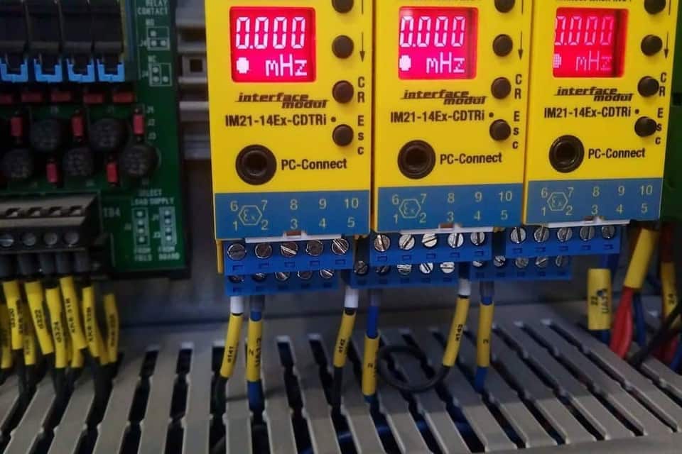
Refinery process areas are classified, and the control system has to cross that boundary without carrying energy into it. We design intrinsically safe circuits and specify the equipment that terminates them: isolating barriers and interface modules rated for Zone 2, cable and gland selection, segregation of intrinsically safe and non-intrinsically safe wiring inside the cabinet, and the loop calculations that prove the circuit stays within the ignition limits.
The part that is most often got wrong is not the barrier. It is the documentation trail behind it: the descriptive system document that ties each certified field device to its barrier and its cable parameters, kept current as the plant is modified. A classified installation whose records no longer match the plant is not a certified installation, whatever the labels on the cabinet say.
Burner management and safety instrumented systems
Burner management for fired equipment, and safety instrumented functions specified, implemented and verified under the functional safety lifecycle of IEC 61511. We have contributed to the certification of SIL 2 and SIL 3 applications, on HIMA HIQuad, Foxboro Triconex and ABB AC800 logic solvers.
Fired equipment on a refinery is where the safety case is most concentrated and where the automation is least forgiving. The firing sequence, the fuel trains, what a safety integrity level actually constrains and how the proof test interval is arrived at are set out under burner management systems to IEC 61511.
Combined heat and power for refineries
A refinery CHP plant is a refinery utility before it is a power plant. Our work on one has covered gas-fired boilers, a 260 t/h circulating fluidized bed boiler firing petroleum coke, steam turbines, coordinated plant load control, and island mode operation that keeps the refinery running when the grid connection is lost.
That ordering matters in the control design. The plant is dispatched to hold steam headers and refinery demand first and electrical output second, so the load controller cannot be tuned as if it were on a merchant station. The behaviour on loss of the grid connection — the transfer that keeps the refinery's own supply alive while the external network is gone — is described under island mode operation, and the efficiency and balance calculations that run on top of it under plant performance calculation.
Gas distribution and metering
A gas distribution station is a small plant with a large consequence. The control system has a short list of jobs and no tolerance for doing any of them approximately: hold the outlet pressure through the regulating streams and the stand-by stream behind them, supervise the slam-shut and relief devices rather than merely house them, and present the metering to both the supplier and the consumer in a form neither of them can argue with.
The measurement side is where automation and commerce meet. Flow computers correct volume for pressure and temperature, the correction has to be auditable, and the station's data has to reach the plant historian and the commercial system without either of them becoming the other's source of truth. We treat commercial metering as a data source of its own alongside the control system, which is how the balances described under MES and production data systems are built.
Emissions and particulate control
Electrostatic precipitators and baghouse filters: design, P&ID, cabling, panel design, specifications and the control that runs them, integrated into the plant control system rather than left as an island.
Leaving them as an island is the usual arrangement and the reason emissions excursions are explained after the fact instead of prevented. A precipitator whose field voltages and rapping cycle are trended against boiler load tells you about the fuel and the combustion long before the stack monitor does.
Changing a control system on a plant that cannot stop
Almost nothing in this industry is built on an empty site. The work is done on a plant that is running, or during an outage measured in days, against a permit system, with somebody else's production at risk if it overruns.
What that imposes on the engineering is specific and unglamorous. The cutover is designed and written down before the outage, not improvised during it. The old system stays able to run the plant until the new one has been proved, which means the changeover is staged rather than total. Loop checking is done against a schedule that can be audited at the end of a night shift by somebody who was not there at the start of it. And every deviation found in the field goes back into the drawings the same week, because the next person on that plant will believe them.
The habit that survives from this is a bias towards proving things rather than assuming them, which is also how the protections get tested — see factory and site acceptance testing and control system cyber security for the access and backup side of working on an operating plant.
Data to the people who need it
Process data collected from control systems and from commercial metering, archived, and delivered to the departments that act on it — unit efficiency to the process engineer, emissions to the environmental engineer, cost and consumption to the finance department.
Platforms
Emerson Ovation · ABB Industrial IT 800xA · ABB Symphony · Siemens PCS7 · Yokogawa Centum VP · HIMA HIQuad · Foxboro Triconex · Honeywell PHD · OSIsoft PI System