
Compliance and Testing
We went through this ourselves
ISYSTEMS AUTOMATION is not a test laboratory. We are a manufacturer that had to get eleven products through EU conformity assessment, and built the test capability to do it.
The first round did not go well. Early-revision boards came back with a punch-list: resets under fast transients on one module, lamp flicker on the dimmer, analog input deviations under conducted RF, a manual restart needed after electrostatic discharge to a USB shell, and a dielectric breakdown on a relay-to-SELV barrier.
Four months of engineering followed. Opto-isolators went from 2.5 kV to 8 kV. Isolated DC/DC converters went from 1.5 kV to 6 kV. Creepage and clearance were widened between SELV and mains-related circuitry. Common-mode chokes went onto the dimmer AC path, ferrite beads with RC damping onto every LED output, a GND / GND_USB split into the USB-C path, ferrite and LC filtering onto the 24 V input of every module. Relay coil and logic supply rails were separated. The cable specification in the manual changed to shielded RS-485 and shielded analog.
The second round came back clean. Eleven EU Declarations of Conformity are issued and the hardware ships.
One test worth describing
During the first electric-strength pass, a sample broke down at about 2.1 kV on the relay-to-SELV barrier, and failed again on retest at a lower threshold. It turned out to be the very first PCB revision — an early prototype with a known issue around the relay output area, never released into production. It was quarantined, labelled, and the test repeated on the production-revision board, which passed the reinforced-insulation requirement.
The lesson went into the process: every test record names the PCB revision it was performed on. A result that does not name its revision is not a result. It is the most common way a compliance file quietly becomes worthless.
Electrical safety testing to EN 62368-1
Directive 2014/35/EU is assessed under Module A: the manufacturer performs the conformity assessment and signs the declaration. No notified body exists under the Low Voltage Directive and none is required. What the directive does require is that the testing behind that signature is real.
The following are run on our bench:
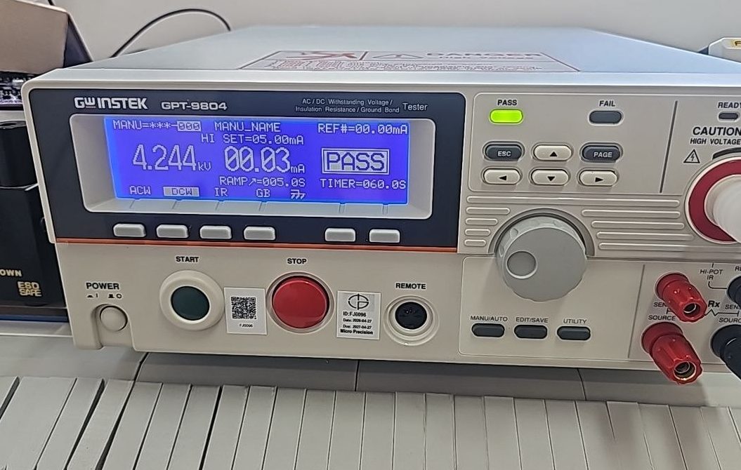
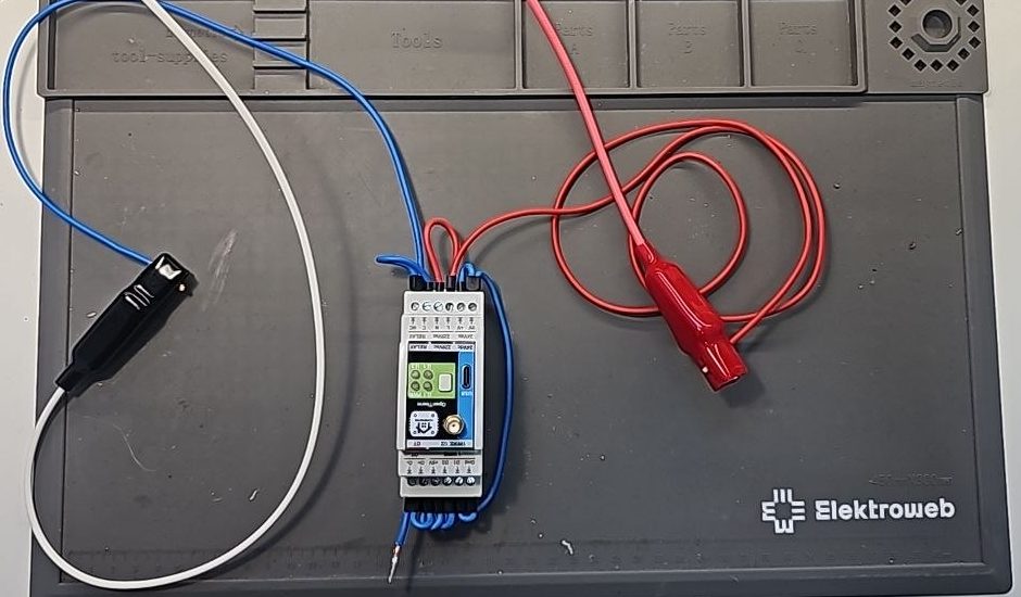
Electric strength, clause 5.4.9. Dielectric strength across every isolation barrier between mains-side and SELV circuits, at the reinforced-insulation test level, 60 s.
Insulation resistance, clause 5.4.10. 500 V DC for 60 s across the same barriers, against the reinforced-insulation minimum.
Touch current, clause 5.7. At 1.06 times rated mains voltage, both polarities, at every accessible terminal, against the 0.25 mA r.m.s. limit.
Temperature rise, clauses 5.4.1.4 and 9. Components instrumented with K-type thermocouples, equipment in worst-case operating mode, measurements stabilised over one hour and corrected to rated ambient per Annex B.3. Assessed against the lower of the component datasheet maximum and the Table 9 limit — which is the part that gets skipped, and it is usually the datasheet that governs.
Single-fault conditions, Annex B.4. Defined faults applied one at a time: supply short, output short, load short, over-voltage on inputs, watchdog disabled, mains over-voltage transient. Checking that no fire, no electric shock hazard and no hazardous energy at an accessible terminal results.
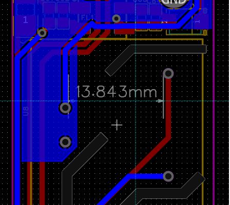
Creepage and clearance, clause 5.4.2. Each insulation path measured on the assembled board against Tables 11 and 14 for the applicable working voltage, overvoltage category, pollution degree and material group. Measured on the board, not read off the layout file — the two differ more often than expected.
EMC screening
Our emissions equipment is a handheld spectrum analyser with near-field probes. That is not a calibrated EMI receiver, and absolute levels against limit lines are not reported from it.
What it does well is find the source and prove the fix:
- Locating the origin of an emission on a populated board
- Before-and-after comparison across a design change
- Confirming that a filter, a ferrite or a ground rework did what it was meant to do
An accredited laboratory report tells you which frequency failed and by how much. It does not tell you which loop on the board is radiating. That translation is the work, and it is what four months went into on our own hardware.
Directive scope and technical documentation
Scope is where it usually goes wrong. Two cases that recur:
A product runs entirely on SELV, so the Low Voltage Directive looks inapplicable. But its relay contacts can switch user-supplied 250 V AC, and that brings it into LVD scope. Of our own eleven products, nine are in scope and only two are outside — several of those nine have no mains input at all.
A product has Wi-Fi. Under the Low Voltage and EMC Directives the manufacturer self-declares and no notified body is involved. Under the Radio Equipment Directive that holds only if the harmonised standards are applied in full; otherwise a notified body is mandatory. The three routes are not one route.
Technical files are assembled to survive a market surveillance request rather than to fill a folder: risk assessment, test records, design documentation and the declaration itself, structured so that each certified hardware revision is tied to a controlled PCB revision identifier and archived manufacturing files, and every declaration names the hardware revision the assessment was performed on.
Cyber Resilience Act
Regulation (EU) 2024/2847 obliges manufacturers of products with digital elements to report an actively exploited vulnerability within 24 hours of becoming aware of it, and to file a full notification within 72. From 11 September 2026, manufacturers of products with digital elements must report an actively exploited vulnerability within 24 hours of becoming aware of it and file a full notification within 72.
The clock starts at awareness, not at confirmation, and the record of when awareness began is the first thing an authority asks for.
The procedure we operate for our own line covers:
- Named reporting officer and deputy, with authority to file
- The awareness timestamp, and where it is recorded
- Internal deadlines tighter than the regulatory ones, with reserve
- An incident register: what is logged, and for how long
- CycloneDX SBOM generated in CI on every build, held in the technical file
- Monthly reconciliation against published vulnerability sources
- A coordinated disclosure policy and a monitored security contact
- The distinction that saves work: a vulnerability reported by a researcher and not being exploited is not notifiable under Article 14
For DCS and safety systems on operating plants we maintain a separate industrial control system cyber security practice that complements this manufacturer procedure.
What this is not
We are not accredited to ISO/IEC 17025, we are not a certification body and we are not a notified body. We do not issue certificates.
Our test records do not replace testing at an accredited laboratory where a conformity assessment route requires it.
Equipment
| Instrument | Used for |
|---|---|
| GW Instek GPT-9804 hi-pot and insulation resistance tester | Electric strength, insulation resistance |
| Programmable AC source | Rated and over-voltage conditions, touch current |
| Calibrated true-RMS multimeter with K-type thermocouple probes | Temperature rise, electrical measurement |
| Calibrated calliper and creepage gauge | Creepage and clearance on assembled boards |
| Handheld spectrum analyser with near-field probes | Emission source location, before-and-after comparison |


Instruments are calibrated externally and carry current calibration labels
Measuring instruments are calibrated with traceability to ISO/IEC 17025.
Standards and legislation
| Reference | Scope |
|---|---|
| EN 62368-1:2020+A11:2020 | Electrical safety, audio/video and IT equipment |
| EN 55032 / EN 55035 | Emissions and immunity, multimedia equipment |
| EN IEC 61000-4-2 / -3 / -4 / -6 | ESD, radiated RF, EFT/burst and conducted RF immunity |
| EN IEC 63000 | Technical documentation for RoHS |
| Directive 2014/35/EU | Low Voltage |
| Directive 2014/30/EU | Electromagnetic Compatibility |
| Directive 2014/53/EU | Radio Equipment |
| Regulation (EU) 2024/2847 | Cyber Resilience Act |