
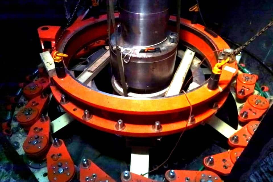
Hydro Turbine Control and Protection
A hydro unit is a control problem with a water column attached. The governor can only move as fast as the penstock will tolerate, and every decision about speed of response is really a decision about pressure surge.
We have worked on hydro units with Siemens S7-300, S7-1500 and S7-1200 under TIA Portal, and with Yokogawa Centum VP, on Pelton machines with nozzle and deflector control.
Unit control
Nozzle control with staged cut-in — the second nozzle brought in at a defined opening of the first — hydraulic cylinder positioning through the governor block and actuator, oil pressure unit management, and the pre-turbine and bypass valve sequence that equalises pressure before the machine is opened.
Start-up is not instantaneous and should not pretend to be: the regulating oil system is warmed by heating the drain tank hours in advance and then cycling the hydraulic cylinder through full travel with holds at each end, because a governor working on cold oil is a governor with a different response than the one that was commissioned.
Protection design and voting
Protection is a set of decisions about what a single failed sensor should be allowed to do. On the unit above:
| Protection | Setting | Voting |
|---|---|---|
| Overspeed | 600 rpm | 2 sensors, 1 out of 2 |
| Bearing oil bath temperature | 65 °C | 2 sensors, 1 out of 2 |
| Generator stator copper temperature | 95 °C | 3 sensors, 1 out of 3 |
| Generator stator iron temperature | 95 °C | 3 sensors, 1 out of 3 |
| Oil pressure unit accumulator pressure, low | 16.3 kgf/cm² | single |
| Oil pressure unit accumulator pressure, high | 29 kgf/cm² | single |
| Drain tank oil level, low | 150 mm below normal | single |
| Drain tank oil level, high | 115 mm above normal | single |
| Nozzle cylinder spool position mismatch | — | comparison |
| Speed sensor mismatch | — | comparison |
Plus generator electrical protection, outgoing 6.3 kV line protection, generator breaker failure, and excitation system failure.
Two-out-of-three on stator temperature and one-out-of-two on overspeed are not arbitrary. They are a judgement about which way to fail: a spurious trip on a generator winding is cheap, a missed overspeed is not.
Failure modes we test for
A protection scheme is only as good as the failures it has actually been exercised against. On a unit shutdown condition we test, one at a time:
- failure of the governor block, including loss of its action on the actuator
- failure of the actuator itself
- sharp loss of oil pressure in the oil pressure unit
- loss of the 0.4 kV auxiliary supply downstream of its automatic transfer
- failure of the DC supply unit
- failure of the unit controller or of its I/O subsystem
Each is applied deliberately, with personnel stationed at the governor stop coil and at the pre-turbine valve to close them by hand if the auxiliary supply goes with it.
Telecontrol and remote operation
Unattended hydro plants are operated over telecontrol links, and the link is part of the plant. We test it as such: channels disconnected one at a time, then two at a time in different orders, then three, checking each time that the unit stays stable and that remote monitoring survives. Transfer between primary and backup channels has to be bumpless, and the only way to know it is is to break the primary while the machine is running.
The harder question is what the plant does when it loses the link to the head node entirely and runs blind until a process setpoint stops it. That behaviour should be a designed decision, not a discovered one.
Related
Island mode and load rejection are covered under Island Mode Operation. Test programmes and acceptance are under Factory and Site Acceptance Testing. Telecontrol redundancy and loss-of-link behaviour are under Control System Cyber Security.